Copper Alloy Inserts in Injection Molds: What They Cool and What They Cost
October 18, 2026
Cooling time is often the biggest share of an injection molding cycle. In most molds cooling lines handle it, but some spots stay hot because water cannot get close. A deep core, a thick boss, a thin steel rib around a hot gate or an insert in a tight corner all slow the cycle. A copper alloy insert gives those spots a path for heat. This guide covers what these inserts do, which alloys are used and what a buyer should say on the RFQ.
What a copper insert does
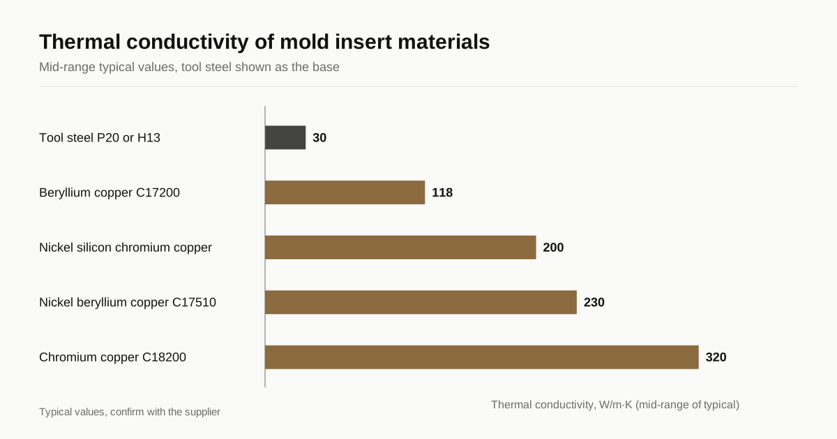
Tool steels such as P20 and H13 conduct heat poorly, roughly 25 to 35 W/m·K. Copper alloys conduct several times better. A small insert of copper alloy placed in a hot spot draws heat away and passes it to a cooling channel, so the plastic around it cools faster and more evenly. The insert is a heat bridge, not a heat sink, because it only works when it connects to flowing water.
Faster cooling at the hottest point can shorten the cycle. It can also reduce warpage and sink marks caused by uneven cooling. The gain depends on the part, the plastic and the cooling design, so a thermal or mold flow analysis is the right way to size it. Claims of fixed cycle time savings are not reliable.
Alloys and typical properties
Typical published values, rounded. They vary by supplier, temper and product form.
| Material | Thermal conductivity, W/m·K | Typical hardness | Notes |
|---|---|---|---|
| Tool steel P20 or H13 | 25 to 35 | 30 to 50 HRC | The mold base reference |
| Beryllium copper C17200 | About 105 to 130 | About 36 to 42 HRC aged | Hardest, strongest copper insert alloy |
| Nickel beryllium copper C17510 | About 200 to 260 | About 95 to 100 HRB | Higher conductivity, softer |
| Nickel silicon chromium copper | About 200 | Roughly 90 to 100 HRB | Beryllium-free option |
| Chromium copper C18200 | About 320 | About 75 to 85 HRB | Best conductivity of the strength alloys, softest |
Conductivity and hardness trade against each other: the harder alloys conduct less. See the copper grade reference for the figures this site publishes for C17200 and C18200.
Where copper goes in the mold
Core pins and cores. Slender cores are hard to cool with water. A copper alloy core pin in contact with a cooling channel removes heat from deep ribs and bosses.
Gate areas. The area around a hot gate stays hot. A copper insert gives a path for heat.
Deep cavities and corners. Spots far from water lines benefit most.
Inserts that join cooling lines. Copper bridges between channels in awkward places.
Not at the parting line. The parting line, shut-offs and sliding surfaces need hardness and wear resistance. Copper alloys are softer, so mold makers keep them inside the cavity away from sealing edges.
Fit and thermal contact
Most thermal failures of copper inserts are not material failures. They are fit failures: a gap, a rough bore or a loose pin that leaves the insert thermally isolated from the steel around it.
Heat moves from the insert into the steel only if the two touch tightly. An air gap works as an insulator. A good fit is a press or shrink fit with controlled interference. Copper expands more than steel, about 17 against 11 to 12 µm/m·K, so the fit tightens as the mold warms and loosens as it cools. Mold makers account for this in the interference.
Surface finish on the mating faces matters too. A smooth, flat fit surface gives more contact area. Specify roughness and tolerance on the fit diameter, for example Ra 0.8 µm and a stated interference fit. For general guidance on holding such dimensions see copper machining tolerances.
Plating and wear
A bare copper surface in contact with plastic wears and can react with some resins. Nickel plating, often electroless nickel 10 to 25 µm, gives a harder, more corrosion resistant face. Chrome or other hard coats are used for abrasive resins. Plating adds thickness, so dimension tolerance must allow for the build. Corrosive resins such as PVC are a reason to specify a plated insert. Copper plating thickness specification covers how to write it.
Polishing is a mold maker’s job. Copper polishes well but scratches easily, so specify who finishes the cavity face and to what grade.
Machining the inserts
Most inserts are turned, milled and ground, or cut by wire EDM. See wire EDM against milling for copper parts. The aged alloys are hard and abrasive. A common route is to machine in the solution treated condition and age afterwards, with a size allowance for movement. Copper tempers explained covers the codes.
Beryllium copper brings handling requirements for dust. Say so in the RFQ, and read machining beryllium copper C17200 for the controls. Some mold makers prefer to avoid it, and beryllium-free copper alloys lists the options and what each gives up.
When an insert is not worth it
Not every hot spot justifies copper. Before ordering, check four things.
- Is the hot spot really driving cycle time? Thermal analysis or measurement on the running mold shows which area limits the cycle.
- Can a cooling line reach it instead? A baffle, bubbler or deeper channel may do the same job for less.
- Is the geometry stable? If the part design will change, an insert made to the old shape becomes scrap.
- Can the insert see enough flow? Copper only helps if it touches a cooling channel. An insert with no heat path just heats up.
Where the answer is yes to all four, an insert is cheap compared with a lost production hour. A well placed copper alloy insert in a core is among the lowest cost improvements a mold can get.
Maintenance and life
Copper inserts are soft and need care. They scratch on cleaning, dent in handling and can corrode in wet storage if unplated. Store them dry and oiled with a vapor corrosion inhibitor suited to copper, and keep spare inserts for the parts that wear. Replace worn or damaged inserts promptly. A cooling water leak behind an insert damages both the part and the mold, so check seals and O-rings at every service. Where the insert carries a cooling channel, a pressure test after repair is cheap insurance, and cold plate leak testing covers the method.
Alternatives
Aluminum alloys conduct about 130 to 170 W/m·K and are used for prototype molds, with lower wear life. Conformal cooling channels, made by metal additive manufacturing in steel, follow the part shape but cost more. A copper insert is the middle path: cheap, quick to make and easy to replace.
Writing the callout
Insert, C18200 chromium copper, temper TH04.
Fit diameter: 12.000 +0.018 / +0.012 mm (interference), Ra 0.8 µm.
Electroless nickel 15 µm on molding surface, mask the fit diameter.
Edges broken 0.2 mm. Deburr and clean, no embedded abrasive.
State the alloy, the temper, the fit and the plating by area. If hardness is critical, add a number. See how to specify copper on a drawing.
Checklist for the RFQ
- Name the alloy and temper, and say if a beryllium-free option is acceptable
- Give fit tolerances and surface finish on the mating faces
- State plating or coating, thickness and masked areas
- Say whether the shop or the mold maker finishes the cavity face
- Mark critical dimensions that must hold after aging
- Give the resin if it is corrosive or abrasive
- Quantity and drawing revision, because mold changes are frequent
Send the drawing through the RFQ form. We match it with up to 3 shops that cut copper and reply within 24 business hours.
Frequently asked questions
Why use a copper insert in an injection mold?
To remove heat from a spot that steel cools slowly, such as a deep core, a thick boss or the area around a gate. Copper alloys conduct heat several times better than tool steel, so the plastic there solidifies sooner, which can shorten the cooling time and cut warpage.
Which copper alloys are used for mold inserts?
Beryllium copper C17200 and C17510 are the classic choices, with chromium copper C18200 and C18150 and nickel silicon chromium coppers as beryllium-free options. The choice trades thermal conductivity against hardness and wear resistance.
Do copper inserts wear out faster than steel?
Yes, at sealing and rubbing surfaces. Copper alloys are softer than hardened tool steel. Mold makers keep copper out of parting lines and shut-offs, and plate the insert with nickel or another hard layer where it touches plastic or slides.
Need a quote for this part?
Send the drawing. We match you with up to 3 copper shops and reply within 24 business hours.
Get matched with a copper machining shop