Machined Copper Induction Coils: Skin Depth, Cooling and Joints
October 17, 2026
An induction coil is a copper conductor that carries high frequency current and heats a metal part without touching it. It is part of the tool, not a consumable, and its shape decides where the heat goes. Coils are often bent from copper tube, but machined coils from solid copper are common for repeatable shapes and for the connections and housings around them. This guide covers the specifications that matter when a shop cuts or joins copper for an induction heater.
How a coil works and why copper
An alternating current in the coil produces a changing magnetic field. That field induces currents in the workpiece, and those currents heat it. The coil must carry large current at high frequency with little loss, which is exactly what copper does best.
The coil is also hot. Its own resistance and the heat radiating back from the workpiece load it with energy. Copper loses conductivity as it warms, about 0.4 percent per degree Celsius, so an uncooled coil heats itself into higher resistance and more heat. Water cooling prevents that. Most coils are therefore hollow, with water running through them.
Skin depth sets the wall
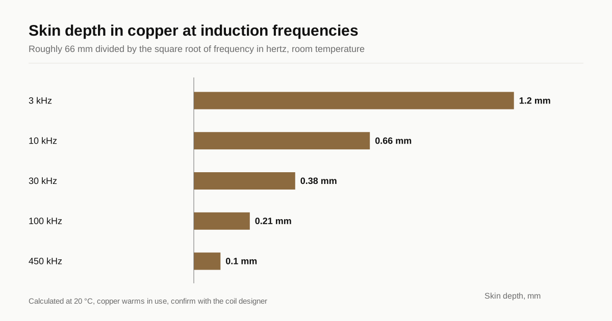
At high frequency, current flows only in a thin layer at the surface of a conductor. The depth where it falls to about 37 percent of its surface value is the skin depth. For copper at room temperature it is roughly 66 mm divided by the square root of the frequency in hertz.
| Frequency | Skin depth in copper | Meaning for the coil |
|---|---|---|
| 3 kHz | About 1.2 mm | Thicker walls carry current |
| 10 kHz | About 0.66 mm | Walls near 1 mm work |
| 30 kHz | About 0.38 mm | Thin wall still carries it |
| 100 kHz | About 0.21 mm | Surface finish becomes important |
| 450 kHz | About 0.10 mm | Very thin layer, smooth surface needed |
Skin depth is a rule of thumb, and the coil designer decides the wall. In practice a wall of 1 mm or more is common for strength and for flow. Machined parts follow the same rule: the current-carrying surface faces the workpiece, and the cooling channel sits behind it at a depth of at least a skin depth or two. The design is the buyer’s. The shop’s job is to hold what the drawing says.
How coils are made
Bent tube coil. Copper tube, usually 6 to 12 mm outside diameter with a thin wall, wound or bent to shape. It is cheap and quick, and it varies from coil to coil. Joints at the leads are brazed.
Machined solid coil. The profile is cut from copper plate or bar by milling or wire EDM. Channels are drilled or milled, then closed with a brazed cover or plugs. It repeats accurately and handles shapes tube cannot, such as single turn rings, flat coils and coils with a precise air gap. See wire EDM against milling for copper parts for how the profile is chosen.
Fabricated assembly. Machined blocks, tube and bus connections brazed together. Lead blocks, water manifolds and mounting plates are CNC parts joined to the coil.
Typical parts a shop is asked to make
Induction heating gear uses more copper than the coil alone.
- Single turn and multi turn coils cut from plate or bar, with drilled cooling channels
- Lead blocks and water manifolds that connect the coil to the supply and the coolant lines
- Terminal and bus connectors between the heater’s output and the coil, which follow copper busbar rules
- Mounting plates and spacers that locate the coil and keep a fixed air gap
- Scanning and hardening inductors with a spray quench ring built into the same body
- Melting furnace cooling coils wound from heavy tube and supported by machined clamps
Each follows the same logic: copper for the current path, water in the middle, joints that hold pressure and edges that do not arc.
What goes wrong in service
A coil lives a hard life, and the causes of failure repeat. Knowing them helps you write a better drawing.
Arcing between turns or to the workpiece. Sharp edges and sloppy gaps start it. Radiused edges and a held air gap prevent it.
Cooling water leaks at brazed joints. Poor fit, trapped flux or a thin wall at the braze cause it. The drawing should state wall thickness and braze joint design.
Blocked channels. Debris from machining or from the water circuit stops flow, and the coil overheats within seconds. Clean channels and a filter in the circuit are cheap protection.
Fatigue cracks at the leads. Vibration and thermal cycling crack thin walls near joints. A thicker wall or a supported lead reduces the risk.
Overheated surface. Poor coolant flow or a wall that is too thick between water and working face leaves the surface hot. Channel position is a critical dimension for this reason.
Machining specifications that matter
- Working surface finish. The face toward the workpiece carries the current. A smooth finish, often Ra 1.6 µm or better, avoids hot spots and arcing. See copper surface finish.
- Edges and corners. Sharp edges concentrate field and heat. Specify a radius, for example 0.5 mm minimum, on edges facing the part.
- Air gap tolerance. Heating pattern depends on the distance between coil and workpiece. A tolerance of ±0.1 to ±0.25 mm on the working profile is typical.
- Channel position. Channel centerline and wall thickness at the working face are critical. Show them as dimensions with tolerance.
- Slit gaps. The gap in a single turn coil sets insulation and field. Cut it by wire EDM, hold the width and keep it clean.
- Flatness of joint faces. Brazed and bolted joints need flat, clean mating faces.
Joining and sealing
Cooling channels must not leak. Silver brazing is the usual method for joints in coils, in a furnace or by torch. C12200 and C10200 are safe for brazing, and C11000 needs care in hydrogen atmospheres. The grade choice is explained in C12200 phosphorus deoxidized copper. Brazing anneals the copper, so coils are soft. They should not be asked to carry structural load.
Every closed cooling circuit needs a pressure test, often with water or air at a stated pressure and hold time. Cold plate leak testing shows how to write it. Joining machined copper parts covers filler and fit.
Burrs and cleanliness
Burrs inside channels can break free and block a nozzle or the cooling circuit. Chips left in the channel do the same. Flush and clean after machining and say what flow or particle check you want. See deburring copper parts.
Plating and insulation
Coils are usually bare copper or have silver plating on the connection surfaces to reduce oxidation and contact resistance. Some coils have ceramic or epoxy insulation between turns to prevent arcing. These are applied after machining and brazing, so state them on the drawing with masking. Copper plating thickness specification covers the callout.
What to write on the RFQ
- STEP model with coil profile, channels and leads
- Copper grade and temper, with the brazing atmosphere if known
- Working surface finish and edge radius
- Air gap and channel position tolerances
- Joint method and any pressure test with value and hold time
- Cleanliness requirement for the channels
- Plating and insulation by area
- Quantity and whether the coil repeats
Stock tube and bar sizes matter too. See copper stock forms. For the current carrying parts that connect coils to the supply, the copper busbar design guide applies. Send the drawing through the RFQ form. We match it with up to 3 shops that cut copper and reply within 24 business hours.
Frequently asked questions
Why are induction coils made of hollow copper tube?
The current runs in a thin layer near the surface, so the inside of the conductor carries almost nothing and can be a water channel. Cooling water removes the heat that the coil's own resistance and the nearby workpiece produce, so the coil does not overheat or soften.
Can an induction coil be machined from solid copper?
Yes, and it is common for single turn coils and complex shapes. The shop cuts the profile, drills or mills cooling channels close to the working surface and seals them with a brazed cover or plugs. It costs more than bent tube but repeats exactly.
What copper grade is used for induction coils?
Tube is commonly C12200 or C11000. Machined solid coils are usually C11000, or C10200 oxygen free copper where the part is brazed in a protective atmosphere. The grade should give high conductivity and be safe for brazing.
Need a quote for this part?
Send the drawing. We match you with up to 3 copper shops and reply within 24 business hours.
Get matched with a copper machining shop